Key Features:
* All models with Dual combustion chamber.
* Stainless Steel chimney/stack, long lifetime.
* High temperature, long lifetime of incinerator.
* Free or minimum installation on site.
* High burn rate, from 10kgs to 600kgs per hour, up to 10ton per day.
* PLC Control Plane for Intelligent operation.
* New Design for pet animal cremation business.
* One year warranty on incinerator and parts in stock.

It features unique and advanced merits with compact size, high burning effect,
Features:
(1) Gasifiedpyrolysis incineration is used for burning many kinds of waste.
(2) Waste can be burned once everyday by gasified incineration.
(3) Gasified incineration, mixed incineration and burnout treatment ensures low emission standard of dust,dioxin etc.
(4) Totally enclosed operation is suitable for treating infectious waste to avoid secondary pollution.
Tel: +86-25-8461 0201
Website: www.hiclover.com
Email: [email protected]
Email: [email protected]
| Items/Model | TS10(PLC) | TS20(PLC) | TS30(PLC) | TS50(PLC) | TS100(PLC) |
| Burn Rate (Average) | 10 kg/hour | 20 kg/hour | 30 kg/hour | 50 kg/hour | 100 kg/hour |
| Feed Capacity(Average) | 20kg | 40kg | 60kg | 100kg | 200 kg |
| Control Mode | PLC | PLC | PLC | PLC | PLC |
| Combustion Chamber | 100L | 210L | 330L | 560L | 1200L |
| Internal Dimensions | 50x50x40cm | 65x65x50cm | 75x75x60cm | 100x80x70cm | 120x100x100cm |
| Secondary Chamber | 50L | 110L | 180L | 280L | 600L |
| Smoke Filter Chamber | Yes | Yes | Yes | Yes | Yes |
| Feed Mode | Manual | Manual | Manual | Manual | Manual |
| Voltage | 220V | 220V | 220V | 220V | 220V |
| Power | 0.5Kw | 0.5Kw | 0.5Kw | 0.7Kw | 0.7Kw |
| Oil Consumption (kg/hour) | 5.4–12.6 | 7.8–16.3 | 10.2–20 | 12.1–24 | 14–28 |
| Gas Consumption (m3/hour) | 6.2–11.4 | 8–15.7 | 9.8–20 | 9.9–26.1 | 10–32.2 |
| Temperature Monitor | Yes | Yes | Yes | Yes | Yes |
| Temperature Protection | Yes | Yes | Yes | Yes | Yes |
| Oil Tank | 100L | 100L | 100L | 100L | 200L |
| Feed Door | 30x30cm | 45x40cm | 55x50cm | 70x55cm | 80x60cm |
| Chimney | 3Meter | 3Meter | 5Meter | 5Meter | 10Meter |
| Chimney Type | Stainless Steel | Stainless Steel | Stainless Steel | Stainless Steel | Stainless Steel |
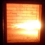
| 1st. Chamber Temperature | 800℃–1000℃ | 800℃–1000℃ | 800℃–1000℃ | 800℃–1000℃ | 800℃–1000℃ |
| 2nd. Chamber Temperature | 1000℃-1200℃ | 1000℃-1200℃ | 1000℃-1200℃ | 1000℃-1200℃ | 1000℃-1200℃ |
| Residency Time | 2.0 Sec. | 2.0 Sec. | 2.0 Sec. | 2.0 Sec. | 2.0 Sec. |
| Gross Weight | 1500kg | 2200kg | 3000kg | 4500kg | 6000kg |
| External Dimensions | 140x90x120cm | 160x110x130cm | 175x120x140cm | 230x130x155cm | 260x150x180cm |
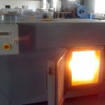
PRIMARY CHAMBER
Heavy-duty steel casing
High quality refractory lining and insulation Large full size top load counterbalanced door
1 x oil/gas fired ignition burners operated on/off
SECONDARY CHAMBER
Heavy-duty steel casing
High quality refractory lining and insulation 2 second gas residence time
1 x oil/gas fired ignition burners operated on/off
CHIMNEY
Heavy-duty stainless steel casing
CONTROL PANEL
Control of primary and secondary burners Temperature Monitoring with 4 digit display
control 0- 12 hours
Integral fan timer control
ANCILLARIES
Operating and maintenance manuals Spares list
KEY FEATURES
•Afterburner Preheat
•Incineration temperatures in excess of 1300°C
•5mm steel casing and fully insulate
•Dense refractory concrete lining rated to 1600°C
An approved plant must have four distinct sections that demonstrate three principles of
Turbulence, Residence Time and Temperature are inbuilt in the plant design .
Overall plant layout. Feed chamber/ charging
Primary Combustion Chamber. Secondary Combustion Chamber. Particulate Scrubbers
Acid Gas Scrubbers The stack/ chimney.
Controlled hygienic, mechanical or automatic feeding methods have to be used which
will not influence the air temperature in the primary and secondary chambers of the incinerator negatively.
No waste is to be fed into the incinerator:
1. Until the minimum temperatures have been reached.
2. If the minimum combustion temperatures are not maintained.
3. Whenever the previous charge has not been completely combusted in the case of batch feeding.
4. Until such time as the addition of more waste will not cause the design parameters of the incinerator to be exceeded.
The primary combustion chamber must:
1. Be accepted as the primary combustion zone.
2. Be equipped with a burner/s burning gas/fuel or low sulphur liquid fuels.
3. Ensure primary air supply is controlled efficiently
4. Ensure minimum exit temperature is not less than 850oC
The secondary combustion chamber must:
1. Be accepted as secondary combustion zone.
2. Be fitted with secondary burner/s burning gas or low sulphur liquid fuel or any suitable fuel.
3. Ensure secondary air supply is controlled efficiently.
4. Ensure flame contact with all gases is achieved.
5. Ensure residence time is not less than two (2) seconds.
6. Ensure the gas temperature as measured against the inside wall in the secondary
1100oC.
7. Ensure the oxygen content of the emitted gases is not less than 11%.
8. Ensure both primary and the combustion temperatures are maintained
A mechanical particulate collector must be incorporated after secondary combustion
chamber for removal of particulate pollutants entrained in the flue gas stream.
a combination thereof:
Cyclone separator Electrostatic precipitators Fabric filters