Bid Bond (2%) : should be submitted (mandatory condition)
Prices: should be itemized based on FOB, CFR Annaba seaport, Algeria
Payment Condition: 100% Bank transfer (CAD) or Letter of Credit (L/C) against presentation of shipping documents
10% Performance Bond unconditioned & confirmed from 1st class Egyptian bank should be submitted (mandatory condition)
Delivery Time is ( xxx ) calendar weeks FOB from P.O issuing date.
Minimum delivery time shall be considered during evaluation.
6
7
Delay Penalties 1% weekly up to max. 5% of the total PO value ( mandatory condition )
Offer Validity is min. ( 3 months from bid due date).
8
Manufacturing Origin is (—————————), Mill Name is (—————————)
Euro1 certificate must be submitted with the shipping documents for materials of European origin
Offer is in compliance with PETROJET bidding documents.
9
10
12
In case of order, Vendor should confirm the following : .
a
Order Confirmation should be submitted within max. 3 working days from P.O date
10% unconditioned performance bond should be submitted within max. 7 working days from P.O date.
In case of Inspection, it shall be done by third party (assigned by Petrojet & on Petrojet’s account) to verify material quality
and all required specifications. An approved certificate from the Third Party Inspector that inspection include
complete data for material specifications must be submitted before shipping to be reviewed
b
c
Supplier Name :——————
Accepted :——————
Signature : ——————
Stamp : ——————
Author Archives: hiclover
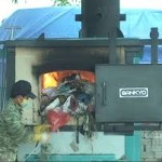
Four representative garbage incinerator
 Waste incineration technology sprouted in the late 1800s. Since the 20th century, with the development of greatly improved and incineration of municipal waste production, waste incineration has become in many countries to develop waste treatment technology.
Garbage incinerator waste incineration is the core technology. Early incinerators by coal-fired boiler manufacturing factory, does not apply to municipal solid waste combustion. With the development of waste incineration process, the waste incinerator technology has matured, the world of various types of waste incinerators reached over 200 kinds, but a wide range of applications, with typical incinerator technology there are four main categories, namely mechanical furnace row incinerator technology, fluidized bed incinerator technology, rotary kiln incinerator technology and pyrolysis and gasification incinerator technologies.
At present, China’s incineration plant construction appropriate to adopt more mature mechanical grate incinerator. In a perfect situation pretreatment system it can also be used a fluidized bed incinerator technology. Rotary and pyrolysis and gasification incinerator less technical applications, can be used as the first two technologies complement.
Mechanical grate incinerator technology
Mechanical grate incinerator garbage incinerator type of early development, through long-term development, the technology has been maturing, high reliability, is currently leading products on the market garbage incinerator.
Mechanical grate incinerator grate structure and movement based on different ways of diverse types, but roughly the same combustion principle, refuse on the grate were stratified combustion, after drying, combustion, post-burn ash discharge of the furnace. Grate will adopt a variety of different ways to make the material layer of garbage continue to be loose and make full contact with the air of garbage, so as to achieve ideal combustion. Garbage grate combustion air is fed from the bottom, depending on the garbage calorific value and moisture into the air grate may be hot or cold. At present, in the form of mechanical grate incinerators include cis push grate furnace, reverse push grate, reciprocating grate furnace and turning rolling grate.
Low mechanical grate incinerator for garbage pretreatment requirements, the garbage calorific value of wide application, easy operation and maintenance. In addition, a single mechanical furnace processing capacity is large, especially for large-scale garbage treatment.
But the mechanical grate incinerator complex mechanical structure, grate material requirements and processing high precision, high cost and maintenance costs.
Fluidized bed incinerator technology
Fluidized bed incinerator technology is a mature technology, which mainly depends on the material of the fluidized bed furnace temperature heat capacity, strong mixing and heat transfer effect, so that rapid warming garbage into the furnace of fire, the formation of the entire bed within the homogeneous combustion. Fluidized bed incinerator technology is the use of fluidized garbage incineration in the furnace a large number of quartz sand as a heat carrier, garbage burning in the furnace suspended.
Fluidized bed incinerator for garbage, there are strict pre-requirements, must be broken into smaller particle size garbage before being burned into the furnace, resulting in high energy consumption and preprocessing strictly odor control requirements. Fluidized bed incinerator waste and bed material in a fluidized state, badly worn, maintenance more frequently, annual operating time than mechanical grate short.
In addition, due to lower current domestic garbage calorific value, difficult individual combustion, co-firing coal need. Advantages of fluidized bed incinerator, due to garbage after crushing to burn fast burn rate, start and stop the furnace and convenient, the general discharge of unburned material released outside were about 1%, is the lowest in several ways of. In addition, the fluidized bed incinerator structure is relatively simple, low cost.
Rotary kiln incinerator technology
Rotary kiln incinerator furnace or water to use firebrick fireplace wall cylindrical roller. It is rotated by the furnace as a whole, so that the garbage uniformly mixed and inclined along the inclination angle end state of the mobile churn. In order to achieve complete incineration of garbage, generally equipped with secondary combustion chamber. When burning garbage, supplied by the upper rotary kiln, rotary drum slowly, so that the garbage constantly flipped to move gradually dry garbage, burn, burn, and then discharged to the slagging device.
Adjust the speed of the rotary kiln, it can affect the garbage in the kiln residence time, and to exert a strong mechanical collision of garbage in hot air and excess oxygen, combustible materials and corruption can be very low slag content. The main disadvantage of this technique is not the amount of waste, fly ash handling difficult, difficult to control the combustion in the current application is less waste incineration.
Pyrolysis and gasification incinerator technology
Pyrolysis and gasification incinerator technology was first used in North America to get this incinerator in Canada called the CAO (Controlled Air Oxidation), it means that the control of air oxidation, in developed countries there are a small number of applications.
Pyrolysis and gasification incinerator has two combustion chambers, two of the combustion chamber by controlling the supply air flow and temperature to achieve complete combustion and pyrolysis and gasification. In the first combustion air supply amount is a 70% -80% of the theoretical amount of air, the temperature control at 600-800 ° C, only allow some solid waste combustion, relying on its solid waste combustion heat so the rest is broken down into a combustible gas; the second fuel room for air volume of 130% -200% of the required amount, the temperature control at about 1000 ° C, the residence time of two seconds, so that the combustible gas combustion, toxic gases completely decomposed, achieve sound.
Pyrolysis and gasification incinerator can effectively inhibit the generation of dioxin, the disadvantage is smaller waste disposal, system complexity, higher operating costs.
The article quoted from China incinerator News
Volcano can become garbage incinerator it?
The idea is good . There toss volcano every day, it appears to be an ideal natural elimination of garbage incinerator. However, I know you want to, but that there is kind of the center of the crater lake of lava lovely. Like some of the shield volcano in Hawaii, they will spray lava slowly to the ground, burning garbage seems very appropriate.
But in fact most of the volcanoes on Earth is called stratovolcanoes, they occasionally have lava flows, but once the heat is too high inside the volcano, the lava “exploding”, but said that the explosion on the explosion. Take one of the Kilauea volcano, the 20th century it erupted 45 times, still often eruption (Figures are it erupted April 23, 2015 in, HVO / USGS). If you’re close to bring garbage thrown into lava, volcanic ash in the distance, just a splash of lava and toxic gases can make you die of.
We want to deal with waste is not insignificant. Said generation American, four pounds per person per day and a half of garbage a year is 250 million tons. If we want to deal with volcanic waste, we need to first lock on the appropriate active volcano, put the garbage there. Few people live near an active volcano, delivered to the garbage will spend a lot of time, money and fuel. You always have to worry about people throwing trash or garbage truck safety.
You have to know that when touched to a large number of normal garbage magma may explode instantly. In 2002, researchers in Ethiopia will be a 30-kilogram bag of garbage thrown into the crater, the result was shocking to see the spectacular explosion. And that package is only equivalent to the United States four garbage home half of the week garbage “yield.” Scientists also observed scene rockfall fall when the lava lake in Hawaii, lava spilled 85 meters of altitude, lava splashing into distant fence and scientific network cameras. So go down garbage, a little too risky.
Not to mention that all the gas you when burning garbage in the volcano, the generated directly into the atmosphere, resulting in a lot of air pollution. And today’s formal regulatory incinerator has systems to ensure that garbage incineration smoke treated before entering the atmosphere. System to prevent the spread of major pollutants is ozone, carbon monoxide and sulfur dioxide.
Human civilization can not be manufactured pieces of debris are thrown into the volcano, there is another reason. That some of the more specialized waste, such as medical waste or nuclear waste, they tend to be particularly dangerous thing. The volcanic lava in a temperature of approximately 700 to 1250 degrees Celsius, which is of course very hot, but the temperature is not enough.
So, with volcanoes act as a garbage incinerator is probably slightly wrong. But still this sentence: a good idea. Please continue to think, to act as a viable method envisaged transfer of volcanic waste incinerator.

Biomedical Waste Incinerator, 10-15 KG
Biomedical Waste Incinerator, 10-15 kg

Manufacturer:
Brand:
Type / Model:
Country of Origin:
Description of Function
The Biomedical Waste Incinerator is used for Incineration of each type of Biomedical Waste.
The Disposal of such Biomedical waste is a very important as it is a dangerous wastes for
human life, and It is only possible with a perfect incinerator.
Operational Requirements
It shall be operated by manual and automated mode.
The combustion efficiency (CE) shall be at least 99.00%.
The combustion efficiency is computed as follows:
C.E.= __%CO2______ x 100
%CO2 + %CO
Emission Standards: Lower emission rates are preferred.
Parameters Concentration in mg/Nm3 (12% CO2 correction
Max total dust 30mg/m3
Max Sulphur Dioxide 200mg/m3
Max Nitrogen dioxide 400mg/m3
Max Carbon 100mg/m3
Monoxide
Minimum stack height shall be 30 metres above ground.
Volatile organic compounds in ash shall not be more than 0.01%.
System Configuration
Biomedical Waste Incinerator, complete unit.
Technical Specifications
Incinerator:
It shall be Electrical or Diesel Fired Incinerator or Controlled Air & pyrolytic.
Type of Waste: Biomedical Waste
It shall have burning capacity 10-15 kg/hr.
Fuel: Diesel
Burner: Monoblock fully automatic burners.
Temperature: Primary Chamber 800 ± 50 oC, Secondary Chamber 1050 ± 50 oC.
Type of Waste: Biomedical waste with moisture content up to 85%.
Destruction Efficiency: 99%.
It shall have separate digital display of temperature for both chambers.
It shall have provision for measuring primary & secondary chamber temperatures using external
thermo coupler.
Secondary chamber gas residence time shall be minimum 1 second at 1050 oC.
Primary Chamber:
Type: Static Solid Hearth
Material of Construction: Mild Steel, 5mm thick
Refractory thickness: approx.115mm thick
Material: Refractory bricks confirming to international standard.
Temperature resistance: 1400 oC
Insulation thickness: approx.115mm thick
Material: Insulation bricks confirming to international standard.
Waste Charging: Manual & Automatic waste charging.
Ash Removal: Manual/automatic
Secondary Chamber:
Type : Static Solid Hearth
Material of Construction: Mild Steel, 5mm thick
Refractory thickness: approx.115mm thick
Material: Refractory bricks confirming to international standard.
Temperature resistance: 1400 oC.
Insulation thickness: approx.115mm
Material: Insulation bricks confirming to international standard.
Waste Charging: Manual & Automatic waste charging.
Emergency Stack:
Type: cylindrical, top mounted on venturi ejector.
Material of Construction: Mild Steel, 3mm thick.
Refractory: 75mm thick castable.
Insulation: 25mm thick castable.
Quencher:
Material of construction of outer body: Mild Steel refractory lined from inside.
Shall have water circulation system with centrifugal pump.
It shall have to reduce flue gas temperature before venturi scrubber.
Shall provide pump motor of suitable capacity.
Air Pollution Control Device – Venturi Scrubber
Type: High pressure jet type.
MOC: Stainless steel – 316L.
Temperature at the outlet: 78-80 oC
Scrubbing Media: Water with 5% caustic
Re- Circulation Pump for Venturi Scrubber
Type: Centrifugal
Application: PP/SS
Piping : PPR
Droplet Separator & Re-Circulation Tank (Integral)
Type: Cyclonic
Application: To separate water droplets from flue gases
Material of Construction: Mild Steel Rubber lined 3mm thick
I.D. Fan:
Type: High pressure centrifugal
Material of Construction: Stainless steel 304, impeller and mild steel rubber lined casting
Drive: Bel
Combustion Fan:
Type: Centrifugal
Modulation: Manual damper control
Material of Construction: Mild Steel
Drive: Direct drive
Burners:
No. of burners: 2 Nos. (1 No. in Primary Chamber and 1No. in Secondary Chamber)
Type: Monoblock fully automatic
Fuel: Diesel
Fuel Oil Storage Tank:
Shall provide suitable capacity of oil storage tank.
Material of Construction: Mild steel.
Facility for visual checking of fuel shall be there.
It shall have diesel consumption monitoring system.
It shall come with diesel oil level indicator, piping with valves & N.R. valve.
Control Panel:
Type: Manual & Automated PLC based control panel with printer & recording device.
Material of Construction: CRCA sheet
It shall have digital temperature controller.
Epoxy powder coated washable paint finish.
It shall have audio-visual alarm system.
Chimney of 30 meters Height:
Material of Construction: Mild Steel
It shall be self-supporting type.
Height shall be 30 meters from ground level.
Paint The chimney is painted externally with two coats of heat resistant aluminum paint
Shall provide ladder till the top.
It shall have 3mm thick rubber lining from inside for protection.
It shall come with aviation lamp, lightening arrestor, stack, drain, inspection platform, sampling
port.
Consumption certificate:
The bidder must submit diesel consumption for a daily operation of 6 hours.
Turnkey:
Prices offered shall be inclusive of all civil works, electrical requirements including cabling and
switches required for installation & commissioning of the equipment.
Bidder shall submit detail drawings, design, and layout plan of civil works.
The bidder shall submit the details of BOQ of civil and electrical works.
Accessories, spares and consumables
All standard accessories, consumables and parts required to operate the equipment, including
all standard tools and cleaning and lubrication materials, to be included in the offer. Bidders
must specify the quantity of every item included in their offer (including items not specified
above).
Operating Environment
The system offered shall be designed to store and to operate normally under the conditions of
the purchaser’s country. The conditions include Power Supply, Climate, Temperature,
Humidity, etc.
Power supply: 220-240 VAC, 50Hz single phase/400 – 420 VAC, 50Hz three phase as
appropriate fitted with appropriate plug. The power cable must be at least 3 meter in length.
Standards and Safety Requirements
It shall have approval of “Pollution Control Board” of purchaser’s country.
All mandatory approvals required for the installation and operation of incinerator shall be done
by the bidder.
Must submit ISO 9001 AND
CE or USFDA approved product certificate.
User Training
Must provide user training (including how to use and maintain the equipment).
Warranty
Comprehensive warranty for 2 years after acceptance.
Maintenance Service during Warranty Period
During the warranty period supplier must ensure preventive maintenance along with
corrective/breakdown maintenance whenever required.
Installation and Commissioning
The bidder must arrange for the equipment to be installed and commissioned by certified or
qualified personnel; any prerequisites for installation to be communicated to the purchaser in
advance, in detail.
Documentation
User (Operating) manual in English.
Service (Technical / Maintenance) manual in English
List of important spare parts and accessories with their part number and costing.
Certificate of calibration and inspection from factory.

Hot Sale Small Scale Waste Incinerators 30 and 50 kgs per hour capacity

| Items/Model | TS30(PLC) | TS50(PLC) |
| Burn Rate | 30 kg/hour | 50 kg/hour |
| Feed Capacity | 60kg | 100kg |
| Control Mode | PLC | PLC |
| Combustion Chamber | 330L | 560L |
| Internal Dimensions | 75x75x60cm | 100x80x70cm |
| Secondary Chamber | 180L | 280L |
| Smoke Filter Chamber | Yes | Yes |
| Feed Mode | Manual | Manual |
| Voltage | 220V | 220V |
| Power | 0.5Kw | 0.7Kw |
| Oil Consumption (kg/hour) | 10.2–20 | 12.1–24 |
| Gas Consumption (m3/hour) | 9.8–20 | 9.9–26.1 |
| Temperature Monitor | Yes | Yes |
| Temperature Protection | Yes | Yes |
| Oil Tank | 100L | 100L |
| Feed Door | 55x50cm | 70x55cm |
| Chimney | 5Meter | 5Meter |
| Chimney Type | Stainless Steel | Stainless Steel |
| 1st. Chamber Temperature | 800℃–1000℃ | 800℃–1000℃ |
| 2nd. Chamber Temperature | 1000℃-1200℃ | 1000℃-1200℃ |
| Residency Time | 2.0 Sec. | 2.0 Sec. |
| Gross Weight | 3000kg | 4500kg |
| External Dimensions | 175x120x140cm | 230x130x155cm |
Vietnam pays heavy price for incinerator imports
 VietNamNet Bridge – While Vietnamese made medical and domestic waste incinerators are finding it difficult to enter the commercial market, foreign-made incinerators have been imported in great numbers.
Vinh Phuc, Phu Tho, Nam Dinh, Thai Binh and Bac Giang provinces have all imported small-scale incinerators to treat domestic waste
The outdated equipment is unsuited to Vietnamese conditions. While many countries now say ‘no’ to incineration technology, Vietnam pays the price for buying the machines.
Trinh Dinh Nang from Hoa Tu Long Thermal Industry Company in Bac Kan province was not surprised after hearing that Vinh Phuc Province’s Science & Technology Department imported an NF105 incinerator worth VND2.25 billion from Thailand and another seven incinerators later.
He knew that Vietnamese preferred foreign-made products rather than domestically made ones. However, he said foreign-made incinerators might do more harm than good.
There are differences in Vietnamese and foreign waste; in many cases, foreign incinerators may even cause problems or be useless.
“In other countries, waste is classified before it is put into treatment. In Vietnam waste is not classified. Treating waste with foreign-made incinerators cannot ensure environmental safety,” he warned.
The inventor of a low-cost incinerator, Nang understands the features and efficiency of incinerators of different kinds. However, he finds it difficult to sell incinerators because buyers prefer foreign made products.
Nang’s incinerator burns garbage at a high temperature of 1,800oC which allows complete burning of waste with the capacity of 30-50 kilos per hour.
Meanwhile, the dust & smoke treatment unit ensures that dioxin and furan will not be recreated during the burning process.
The great advantage of Nang’s incinerator is low operation cost – VND5,000 per kilo when treating waste with diesel and VND2,000 per kilo with waste oil.
The incinerator is the first product of its kind in Vietnam which can satisfy the National Standard No 30 set by the Ministry of Natural Resources and the Environment.
“When I introduced my incinerator in Cao Bang, local officials said they liked it very much, but they did not have money to buy,” he said.
“When I talked about the incinerator in other localities, local officials hesitated to buy it because the incinerator has not been used in other provinces,” he complained.
A thermal technology expert noted that local authorities prefer imports because they get benefits when buying products from overseas.
“No one knows the real value of foreign made products and technologies. It is easy to exaggerate the import price,” he noted.
Dat Viet
http://english.vietnamnet.vn/fms/science-it/139786/vietnam-pays-heavy-price-for-incinerator-imports.html
Pet Animal Crematory Equipment
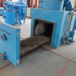
Clover Incinerator update A model incinerator for pet cremation and animal incineration. New design accept independent movable platform in-out incinerator combustion chamber. This new design is valid for model A900 and bigger model.
Tel: +86-25-8461 0201
Email: [email protected]
Email: [email protected]
Email: [email protected]


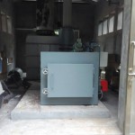
Doubel Combustion Chamber High Temperature Incinerator
All Incinerators are Doubel Combustion Chamber with One Fuel Burner Each. After Burner Technology for Completely Combustion and Cleaner World.
Temperature Range 800 Degree to 1200 Degree in Combustion Chamber. Temperature Thermocouple Monitor and Controller. High Quality Fire Brick and Refactory Cement.

